It’s been several weeks since we showed you the graphics for new high resolution circuit connector modules (FFF-202). However now is finally the time when we have them in the game. In this article I will briefly show you what was done both in the graphics and code, and what new benefits are there for you as players and modders.
I find the 0.15 version of the circuit connector module has following “problems”:
We have been experimenting with the design of how the little pieces which connect to wires should look like. Most of them don’t really make sense in terms of physics, but visually the combinator ones seem to work pretty nicely in my opinion. That, and the circuit connector should be somewhat consistent with the combinators in this regard, so we just used the combinator design from when Albert made the combinators back in 2015 (FFF-88).
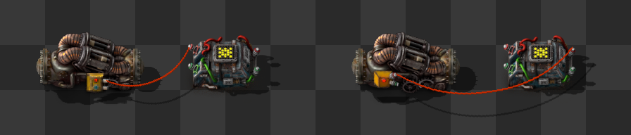
As we already tried to hint in FFF-202 (but we didn’t have a proper picture for it yet because the hr circuit connector wasn’t in the game yet), when you build entities vertically, they would very often only show one colour of wire.

To prevent this from happening, I took a pixel grid in Blender and I tried to always have the connectors far away from each other to prevent this from happening. The same issue happens with combinators, but let’s see if we ever have time to change that.

The system of drawing has slightly changed - now when you connect an entity, you can clearly recognize what it is doing and what is it's state. The rule is: Red/Green LED means write mode - generally stopping/starting the entity. Blue LED means reading mode - generally reading chest contents, reading signal colours, and so on.
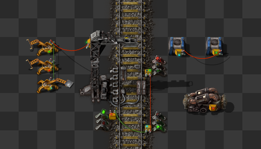
If you only connect to the logistic network, even the wire connection points are going to disappear as you can see on the pump above.
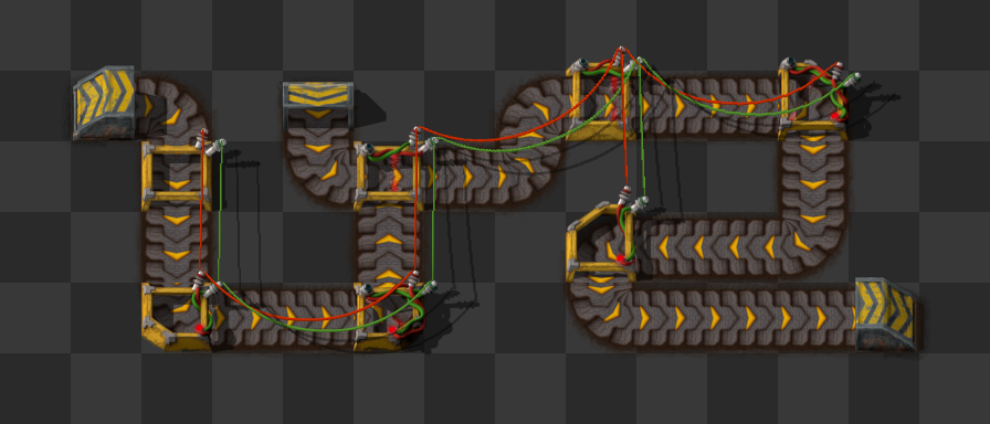
Previously we were using the universal connector on belts, and to support it we made a special layer with a frame to hold it. This just uses another layer and generally looks rather weird.
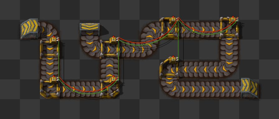
We found it better to just make specific sprites for belts, which should integrate nicer and use less layers.
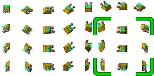
If you ever looked at how the circuit connector module spritesheet actually looks, you would have noticed that there are 32 rotations of it. For the first row, which is just flat on the ground, all of the 8 rotations are useful, but when the box starts tilting, the last three are looking away from the camera and are basically impossible to use.
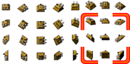
At the same time, on some entities and in some cases it would be really cool to be able to just put the wire connection points at the opposite side of the box.
I put the two things together and made the impossible-to-use rotations just be a flipped version of the useful ones. The picture below is a mockup, the actual spritesheets have separate layers to allow the modularity mentioned above.
The game does not actually utilize all of the 32 rotations, but it’s easier to have them all for future new entities - importantly also new entities added by mods.
When the graphics were finished, I was looking at how could I put the connector in the game. We had good experience with generating the Lua code in combinators, and I wanted to make use of some similar system again, because there is just a stupid amount of shiftings and definitions to be made.
To get all the shifting values, we are using a very similar system to what was described in FFF-202, special pictures from After Effects processed by python scripts. The only real difference is that now After Effects also has to import spritesheets of our existing entities and align them with the shifting values. Luckily, After Effects supports javascript based expressions which makes this work simpler.
var shiftingX = 16;
var shiftingY = 8;
var finalX = transform.position[0]+ (shiftingX * 2);
var finalY = transform.position[1]+ (shiftingY * 2);
[finalX, finalY]
This simple expression just lets me center the sprite and copy the X and Y shifting values from Lua, instead of having to worry about making calculations all the time, and it’s more readable when re-visiting and checking.
With the shifting values ready, the next step is to tell the game to accept them somehow. I wouldn’t dare to try overwriting all of the entries in entities.lua and similar files, simply because it would probably mean massive amount of errors, both by hand or somehow automatically.
So instead Michal (Posila) wrote a python script which generates a new circuit connector file where all of the specific definitions are kept, and refactored the entities so that each entity connectible to the circuit network just grabs the values from the master circuit connector file. Hopefully this makes it more maintainable for the future...
As one of the often used entities in the circuit network, the lamp is getting a high resolution version. The graphics are a work in progress so there will likely be some changes.

As always let us know what you think, just like you have been in the last 4 years (FFF-1) on our forum. We would like to thank you for all the attention and feedback through all this time, it’s really nice to be able to talk about our work, and sometimes even add something we forgot and you mentioned.